
Product Details
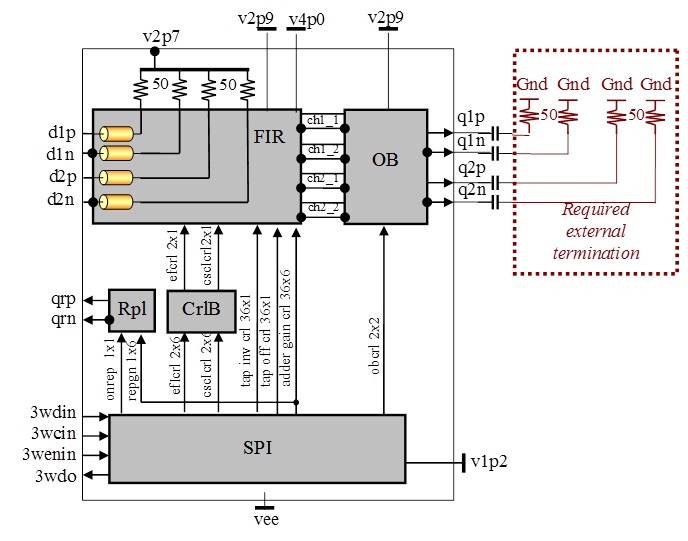
Fig. 1 Functional Block Diagram
This part is now considered obsolete.
Please see ASNT6172-KMN here at: https://adsantec.com/product/asnt6171-kmo-2-2/
The ASNT6172A-KMO is a two-channel differential analog 9-tap FIR filter. It receives two high-speed analog signals through its differential input ports d1p/d1n and d2p/d2n. Each channel of FIR has 9 dual taps. Each tap provides two copies of its input signal with controlled polarities. The signals are then processed by analog adders with controlled weight coefficients to perform the pre-emphasis operation. The resulting 4 analog signals (the first and the second signals from the first and the second channels) are sent to the output buffer block that converts them into two output analog signals delivered to linear differential ports out1p/out1n and out2p/out2n. The first output port presents either individual first signal from any channel, or a sum of both first signals. It can be also completely disabled. The second output port presents the second signals from both channels with the same operational modes. Both ports operate in CML-type mode and require external 50Ohm terminations.
All chip functions are controlled by internal digital signals delivered through a 3-wire serial-to-parallel interface (SPI) that operates in combination with an internal control block CrlB. The chip includes a 1-tap replica Rpl that can be independently enabled and used for initial gain calibration as described below.
FIR
The FIR consists of two identical channels. At the input of each channel there is a differential transmission line that includes 10 identical sections connected in series to provide ten equal delays. The connection nodes of the sections serve as inputs for 9 taps. The ends of the last section have internal 50Ohm terminations to a separate internally generated power supply v2p7. The last section is required for achievement of matching conditions for all taps.
Each tap includes a pair of dual buffers (buf1 and buf2) which allows for generation of two copies of the tap’s input signal with polarities individually selected by 1-bit binary signals chX_inv1 and chX_inv2, where “0” corresponds to a direct output signal and “1” corresponds to an inverted output signal. Dual buffers in each tap can be individually disabled by special 1-bit binary signals chX_off1=”0” or chX_off2=”0”. The buffers of different taps have slightly different gains and internal peaking in order to compensate for transmission line losses. The 9 pairs of delayed copies of the differential input signal with set polarities are then processed by two 2-stage adders in order to create two linear sums of weighted tap signals. The first stage of each adder consists of three 3-to-1 adders and combines 9 input signals into 3 intermediate signals. The second stage combines those intermediate signals into 1 output signal. Identical 3-to-1 analog adders with digital controls of each input’s weight are used in both stages. The control circuitry of the 3-to-1 adder is designed in such a way that the combined weight of all 3 inputs does not exceed the maximum weight of one tap. The control circuitry receives three 6-bit binary signals: the first weight chX_gncYZ1, the second weight chX_gncYZ2, and the maximum possible weight chX_gnmxY, and converts them into another three 6-bit binary signals that control the actual weights of all three inputs. Here X is the channel number 1 or 2; Z is the 2-stage adder number 1 or 2; and Y is the 3-to-1 adder number 1, 2, 3, or 0, where the adders 1, 2, and 3 represent the first stage and the adder 0 represents the second stage.
More information can be found in the product datasheet.