Product Details
This part is now obsolete, and has been superseded by the ASNT8121-KMC which can be viewed here:
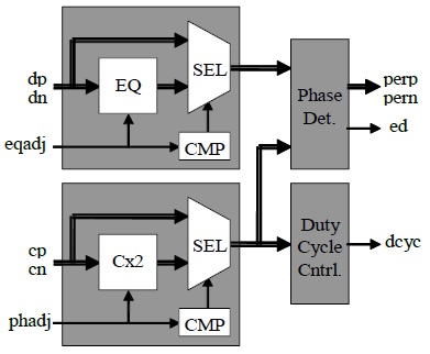
Fig. 1. Functional Block Diagram
The ASNT8120-KMC SiGe IC shown in Fig. 1 provides a differential phase error signal perp/pern that indicates the phase difference between the data dp/dn bit transitions and the edges of the input clock cp/cn. The input data spectrum can be corrected by the equalizer EQ with a frequency response adjustable by the variation of the control input signal eqadj within the voltage range from vcc to vcc-2V. The lower values of eqadj disable the equalizer and send the input data signal directly to the phase detector block PhaseDet. The input clock can be delivered to the phase detector block either directly or through the multiplier by 2 Cx2 with its output duty cycle adjustable by means of the phadj control voltage. The phadj control operates similar to eqadj with a tunable range from vcc to vcc-2V and a multiplication enabling threshold value of vcc-2V.
The phase detector also provides two single-ended signals ed and dcyc. The ed output delivers an analog voltage indicating the number of transitions in the data bit stream. The duty cycle control block DutyCycleCntrl generates the analog signal dcyc that indicates the clock duty cycle deviation from 50%.
The part’s differential input clock and data ports support the CML logic interface with on chip 50Ω termination to vcc and may be used differentially, AC/DC coupled, single-ended, or in any combination. In the DC-coupling mode, the input signal’s common mode voltage should comply with the specifications shown in the electrical characteristics section within the part’s datasheet. In the AC-coupling mode, the input termination provides the required common mode voltage automatically. The output phase error port supports a CML-type interface with on chip 100Ω termination to vcc and may also be used differentially, AC/DC coupled, single-ended, or in any combination. The differential DC signaling mode is recommended for optimal performance.