Product Details
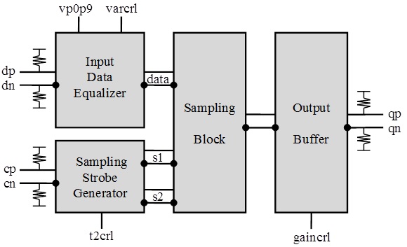
Fig. 1 Functional Block Diagram
The temperature stable and broadband ASNT7113A-KHC SiGe IC is a high-speed track-and-hold amplifier (THA). The IC shown in Fig. 1 performs sampling of an input differential analog signal using two internally-generated strobe signals s1 and s2, and delivers a step-like differential signal to the output. It features an adjustable track period length controlled by the t2crl voltage that modifies the states of internal delay lines. This allows for maximizing the length of the valid output step.
The differential gain of the chip is approximately 0dB, which corresponds to a single-ended-to-differential gain of -6dB. The gain can be adjusted using the external control voltage gain cnrl. The chip supports both AC-coupled and DC-coupled inputs. In the DC-coupled mode, the input common-mode voltage must be equal to vcc for optimal performance of the chip. The input sampled data path includes an equalizer that increases the bandwidth of the chip. The level of equalization is controlled by the external voltage varcrl.
The frequency response and gain of ASNT7113A is also controlled by the positive supply voltage vp0p9 that powers the input buffers of the Track-and-Hold. This voltage defines the common mode of the data signal at the input of the sampling switch and thus the frequency response of the device. Lower voltages result in less peaking in the input buffer and less overall gain of the device. The part’s outputs support the CML-type logic interface with an on-chip 50Ohm termination to vcc and may be used deferentially, AC/DC coupled, single-ended, or in any combination (See POWER SUPPLY CONFIGURATION within the part’s datasheet for details). The differential DC signaling mode is recommended for optimal performance.