Digital circuits are all around us. They are found in smartphones, TVs, laptops, microwave ovens, gaming consoles, digital cameras – in short, in everything modern day electronics. One of the most important components of these circuits are logic gates.
Logic gates are building blocks of digital circuits. They help the digital circuits analyze and process various digital signals.
A typical logic gate has two inputs for incoming electrical signals, and an output for an outgoing electrical signal. It works by comparing the two input signals, and based on Boolean logic, computes and produces a resulting output.
At any given moment, the inputs to logic gates can either be “HIGH” or “LOW”. HIGH inputs are denoted by binary bit “1”, while LOW inputs are denoted by binary bit “0”. Whether an input signal is HIGH or LOW depends on the voltage level of the input signal. System designers set a particular voltage value (or range)for HIGH or LOW signal classification when designing the system.
Like the inputs, the output of a logic gate is also classified as either “HIGH” or “LOW”. However, here the signal classification depends on the result of the computation performed for the inputs.
There are mainly six types of logic gates commonly used in digital circuits today. These include:
- AND gate
- OR gate
- XOR (Exclusive OR) gate
- NOT gate
- NAND (NOT AND) gate
- NOR (NOT OR) gate
Let’s take a look at them one by one.
AND gate
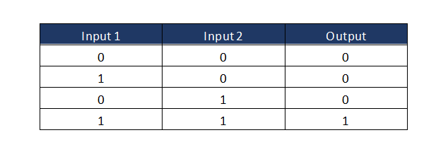
The AND gate gives a “HIGH” output only if both its inputs are “HIGH”. The truth table of AND gate is as follows:

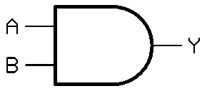
The AND gate is schematically represented as:

OR gate
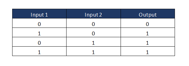
The OR gate gives a “HIGH” output if one or both of its inputs are “HIGH”. The truth table of OR gate is as follows:

The OR gate is schematically represented as:

XOR gate
The XOR gate gives a “HIGH” output if either, but not both, of its inputs are “HIGH”. The truth table of XOR gate is as follows:

The XOR gate is schematically represented as:

NOT gate
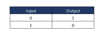
The NOT gate is a special type of circuit that only has one input. It produces an output by simply inverting the input signal. The truth table for NOT gate is as follows:

The NOT gate is schematically represented as:

NAND gate
The NAND gate is basically the combination of AND and NOT gate. The truth table for NAND gate is as follows:

The NAND gate is schematically represented as:

NOR gate
The NOR gate is the combination of OR and NOT gate. The truth table for NOR gate is as follows:

The NOR gate is schematically represented as:

Buy high quality logic gate circuits at ADSANTEC
At ADSANTEC, we stock the best quality electronic and circuit components—including high speed logic gate circuits—for your specialty system design needs. View our product catalogue for more details.