Demultiplexers are commonplace in digital electronics. They are typically found in communication systems, arithmetic logic unit (ALU) circuits, parallel data circuits, and are used in almost all applications that concern data distribution.
This post will provide a quick refresheron demultiplexers to dust off your knowledge of these all-too important combinational circuits.
Overview of Demultiplexers
Let’s start off with the most basic question:
What is a demultiplexer?
Simply put, demultiplexer (DEMUX) is a type of digital switch that takes a single input and routes it to one of severaloutputs.
For example, let’s say you have a computer. And you want to connect this computer to a printer, a fax machine and a pen plotter, so that it can send data to these devices when and as needed.
This is where using a DEMUX comes in helpful.
The circuit will accept data from the computer and will forward it to one of the connected devices (printer, fax machine, or pen plotter) depending on whatever routing instruction you provide it with.
How do you provide routing instructions to a DEMUX?
Every demultiplexer has selector lines. These selector lines are fed with different combination of inputs to yield different routing responses at the output.
So by feeding the right combination of input to a DEMUX, you can instruct the DEMUX to forward the data to the device that you wish to communicate with.

Demultiplexers come in general configurations of 1: 2n, where:
- “n” is the number of select lines
- “2n” is the number of output lines
This way, we have 1:2 demultiplexers, 1:4 demultiplexers, 1:8 demultiplexers,1:16 demultiplexers etc.
The relationship between number of select lines and number of output lines for a demultiplexer is defined as follows:
2m = y
where,
“m” is the number of select lines and “y” is the number of output lines.
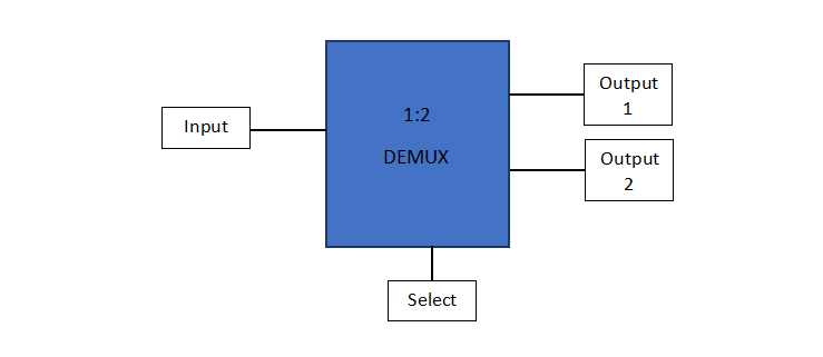
So, for a 1:2 demultiplexer, we’ll have:
- One input line
- Two output lines; and
- One select line
Let’s quickly take a look at how a 1:2 demultiplexer works.

Consider the input as D, select line as S, output 1 as O0, and output 2 as O1.
Then the function table of a 1:2 DEMUX will look something like this:

This shows that when the input to the select line is “LOW”, the DEMUX will route the data to output 1 (O0) and when the input to the select line is “HIGH”, the DEMUX will forward the data to output 2 (O1).
The logic expression for the demultiplexer can therefore be written as:
O0 = S’D
O1 = SD
indicating that a 1:2 demultiplexer (or any other multiplexer for that matter) is basically a combination of AND and NOT logic gates.
This completes our review of demultiplexers.
Buy High Performance Demultiplexer ICs at ADSANTEC
At ADSANTEC, we stock high quality, programmable, digital demultiplexer ICs at affordable prices. View our complete demultiplexer IC range here.