Product Details
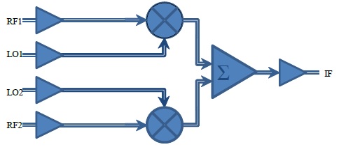
Fig. 1 Functional Block Diagram
I/Q modulators are critical components in the signal chain of modern digital transmitters. I/Q modulators perform the frequency translation that moves a base-band signal to a desired location in the RF spectrum. The I/Q modulator shown in Fig. 1 accepts 2 local oscillator inputs LO1, LO2 representing in-phase (I) and quadrature (Q) components separated by 90°. These two signals are combined with I and Q baseband signals RF1, RF2 in two separate mixers. The outputs from both mixers are then summed to provide a modulated carrier IF.
The part’s output buffers support the CML-type interface with on-chip 50Ω termination to vcc and may be used in either DC or AC coupling modes. The output common-mode voltage level of vcc-0.4V is guaranteed only in case of external single-ended 50Ω DC termination to vcc. The part’s input buffer supports the CML-type interface with on-chip 50Ω termination and can be used in either DC or AC coupling modes. In the first mode, the input signal’s common-mode voltage should comply with the electrical characteristics section of the part’s datasheet. In the second mode, the input termination provides the required common-mode voltage automatically. The differential DC signaling mode is recommended for optimal performance.