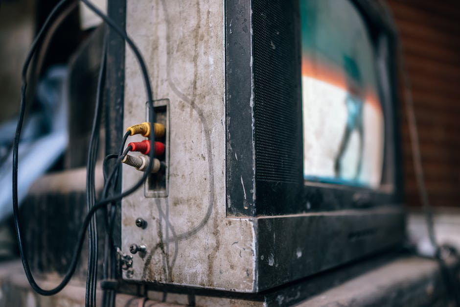
If you grew up in the 80s or 90s, you probably remember the CRT televisions we had in our homes before LEDs took over.
If you’ve ever had CRT televisions, you must also remember connecting their coaxial cables with signal splitters.
But what is a signal splitter and how does it work? Read on to find out.
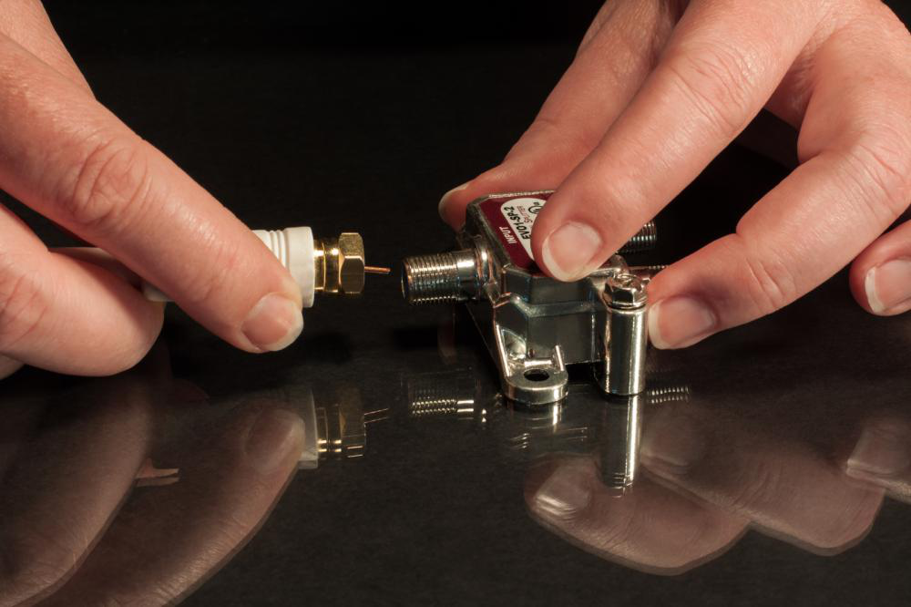
What is a Signal Splitter?
A signal splitter accepts input from the television’s cable and then divides them into ‘N’ ways, sending them to the output ports. For a conventional signal splitter, the number of ports lies anywhere between the range of 2 and 8. What’s important to note is that the signal strength decreases with the increase in port numbers. This means that an 8-way splitter will suffer from greater signal attenuation than a 2-way splitter.
The amount of attenuation that a signal is likely to suffer from is mentioned on the splitter’s output ports. Typically, an 8-way splitter attenuates the signal by 10.4 dB.
Does this have you wondering: can I afford to lose 10.4 dB of the signal in my circuit?
There’s no specific answer to this question; it depends on the splitter’s placement in your circuit. You can afford to lose the signal strength if it won’t suffer from any significant attenuation after the splitter output.
Difference Between Analog and Digital Signal Splitter
The major difference between an analog and a digital signal splitter lies in their frequency range. Analog splitters have a maximum frequency range of 900 MHz. This frequency limitation makes them incompatible with modern televisions dealing with the 720 and 1080 pixel range, as they relatively operate on a 1 GHz frequency range. Transmitting these signals via analog splitters can result in a static picture or complete loss of signal.
While these splitters might not be an ideal choice for the transmission of high-definition images, you can use them for a variety of applications that lie within their operating frequency range, as they’re comparatively more economical than digital splitters.
The transmission of high-definition images led to the development of digital signal splitters, which can transfer signals up to 1 GHz frequency range. They offer a flat frequency response with minimum variations in the output spectrum.
If you’re looking for reliable signal splitters with low power consumption, get in touch with ADSANTEC.
We provide linear signal splitters with a linearity range of 100mV p-p and -1.5 dB differential gains. Our signal splitters provide minimum temperature variations and low jitter at a high temperature range.
In addition to that, we also provide 4-bit ADC, delay lines, clock dividers, Boolean logic gates, and several other electronic components to help you get started with your new project in no time!
Contact us today for customized designs.